Explore laser imaging and photogram principles by adjusting rotor amplitudes, frequencies, phase differences, and lens positions. Visualize how lasers form magnified images interactively with our simulator.
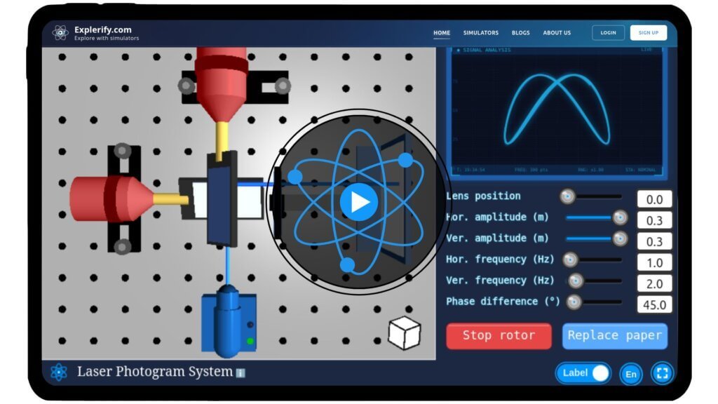
Physics shapes the world around us, often in ways we don’t notice. Imagine being like Dr. Stone, rebuilding technology from scratch using only the fundamentals of physics. Just as he ingeniously built a TV from the basics, you too can explore how lasers, lenses, and rotors work together to form precise images. With our Laser Photogram System Simulator, adjust rotor amplitudes, frequencies, phase differences, and lens positions to see how laser light creates magnified images on paper. Discover the principles of optics and photogrammetry firsthand — experiment like a true physics innovator today!
\[ \begin{aligned} x(t) &= A \sin(a t + \delta) \\ y(t) &= B \sin(b t) \end{aligned} \]
Mathematical description
The laser spot traces a Lissajous figure on the paper based on the horizontal and vertical rotor motions
where:
\( A \) is the amplitude along the X-axis (horizontal rotor)
\( B \) is the amplitude along the Y-axis (vertical rotor)
\( a \) is the angular frequency of the X-axis motion
\( b \) is the angular frequency of the Y-axis motion
\( \delta \) is the phase difference between the two motions
\( t \) is time
Simulator
Dive into the physics of laser imaging with our interactive Laser Photogram System simulator!
Interactive Physics Simulator – Image Formation by Concave Mirror
Share with your friends
Compact User Progress Tracker
🌟 You May Also Like
Suggested experiments and activities based on your progress...
FAQs on Laser Photogram System
Qus 1. What is the Laser Photogram System Simulator?
The Laser Photogram System Simulator is an interactive virtual lab that lets you explore how lasers, rotors, and lenses work together to form magnified images. You can adjust parameters like rotor amplitude, frequency, phase difference, and lens position to observe how laser patterns change on the paper.
Qus 2. How does changing the lens position affect the image?
Adjusting the lens position changes the focal length and magnification of the image formed on the paper. Moving the lens closer or farther from the rotor assembly alters the size and clarity of the projected laser pattern.
Qus 3. Can I zoom and rotate the simulator view?
Yes! You can click and drag to rotate the setup and scroll to zoom in or out. This helps you observe the laser patterns from different angles and understand the 3D arrangement of the components.
Qus 4. What physics concepts can I learn from this simulator?
This simulator helps you understand:
Laser beam propagation
Principles of optics and magnification
Interference and phase differences
The effect of amplitude and frequency on laser patterns It’s a hands-on way to visualize concepts that are often difficult to see in a real lab.
Qus 5. What is the relationship between rotor motion and the laser pattern?
The horizontal and vertical rotor motions control the movement of the laser spot on the paper. By adjusting amplitude, frequency, and phase difference, you can create complex patterns such as Lissajous figures, showing how combined oscillations translate into image formation.
Qus 6. How does this simulator demonstrate photogram principles?
Photogrammetry involves measuring and analyzing patterns formed by light. In this simulator, the laser pattern formed by the moving rotors and lenses demonstrates how light can be used to create precise images, visualize motion, and study interference. It also shows how changing parameters affects image geometry, similar to real photogrammetry experiments.
Qus 7. What are the real-world applications of these principles?
The concepts demonstrated in this simulator are used in:
Laser scanning and imaging
Optical measurement and alignment systems
Photogrammetry for mapping and 3D reconstruction
Laser-based communication and sensors Understanding these principles provides a foundation for careers in optics, engineering, and experimental physics.