Charge to mass ratio with parallel plate capacitor
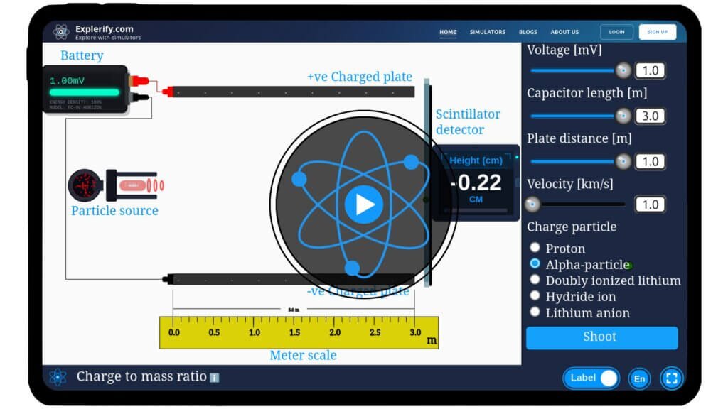
Calculate the charge-to-mass ratio of a particle with our interactive simulator by observing the change in its trajectory height as it passes through the electric field of a parallel plate capacitor.
Charge to mass ratio with parallel plate capacitor
Physics influences our world in remarkable ways, often hidden in plain sight. Curious about how charged particles behave in electric fields? Explore this with our interactive Charge-to-Mass Ratio Simulator featuring parallel plate capacitors. Adjust key parameters, observe particle motion, and uncover the relationship between charge, mass, and voltage. Dive into the science and start experimenting today!
\( y = \frac{qV_p l^{2}}{2mdv^{2}} \)
Mathematical description
where:
\( y \) is the displacement in vertical trajectory of charge particle.
\( q \) is the charge on the particle
\( V_p \) is the voltage across the parallel plates
\( l \) is the length of the parallel plates
\( m \) is the mass of particle
\( d \) is the length of the plate
\( v \) is the velocity of particle
Simulator
Explore the charge-to-mass ratio in our interactive simulator with parallel plate capacitors!
Interactive Physics Simulator – Image Formation by Concave Mirror
Share with your friends
Compact User Progress Tracker
🌟 You May Also Like
Suggested experiments and activities based on your progress...
FAQs on Charge to mass ratio
Qus 1. What is the aim of the charge to mass ratio experiment using parallel plate capacitor?
The aim is to determine the charge-to-mass ratio (e/m) of an electron by observing its deflection in a uniform electric field between parallel plates.
Qus 2. What is the principle behind the charge to mass ratio experiment using parallel plate capacitor?
An electron beam experiences a force in a uniform electric field, leading to vertical deflection. Measuring this deflection helps calculate e/m using motion equations.
Qus 3. Why are parallel plates used in the charge to mass (q/m) experiment?
Parallel plates create a uniform electric field, allowing for precise control and predictable electron deflection.
Qus 4. How is the charge-to-mass ratio (q/m) of a particle derived from its vertical displacement in an electric field?
In this experiment, we are using the Electric Field Method (with parallel plates), where electrons are deflected by an electric field, and deflection is measured on a screen.
1. Force on Electron in the Electric Field
Between the plates, a uniform electric field \( E= V_p/d \) acts (where \( V_p \) is potential across plates, \( d \) is plate separation):\[ F = eE \Rightarrow a = \frac{qE}{m} \]
2. Time of Travel Between the Plates
Let \( l \) be the length of the plates. Time to cross this distance horizontally: \[ t = \frac{l}{v} \]
3.Vertical Deflection While Passing Between Plates
Using equation of motion: \[ y = \frac{1}{2}at^2 = \frac{1}{2} \cdot \frac{qE}{m} \cdot \left(\frac{l}{v}\right)^2 \]
4. Substitute \( E= V_p/d \)
Using equation of motion:\[ y = \frac{1}{2} \cdot \frac{q}{m} \cdot \frac{V_p}{d} \cdot \frac{l^2}{v^2} \] \[ y = \frac{q V_p l^2}{2 m d v^2} \]
Qus 5. What is the typical setup of this experiment?
A cathode ray tube (CRT) or electron gun, parallel plate capacitor, power supply, and screen are used to measure electron deflection due to electric force.
Qus 6. What are sources of error in this experiment?
Misalignment of plates, inaccurate measurement of deflection, or non-uniform electric fields can affect the accuracy of the e/m value.
Hi Tushar,
Yes — the finite size of the capacitor plates causes edge (fringing) effects, making the electric field non-uniform near the edges.
This leads to a systematic error where the actual capacitance is slightly higher than the ideal.
Since it is a systematic error, it does not fluctuate between measurements — it depends only on the plate geometry.
It can therefore be calculated or corrected (for example, using fringe-field correction formulas or by comparing with the theoretical infinite-plate value).
To minimize it, use plates much larger than the separation or add a guard ring to confine the field and restore uniformity.


I think the finite lenght of capacitor plate also adds to uncertainty since field is not uniform at the edge.
Hi Tushar,
Yes — the finite size of the capacitor plates causes edge (fringing) effects, making the electric field non-uniform near the edges.
This leads to a systematic error where the actual capacitance is slightly higher than the ideal.
Since it is a systematic error, it does not fluctuate between measurements — it depends only on the plate geometry.
It can therefore be calculated or corrected (for example, using fringe-field correction formulas or by comparing with the theoretical infinite-plate value).
To minimize it, use plates much larger than the separation or add a guard ring to confine the field and restore uniformity.